Product installation and wiring
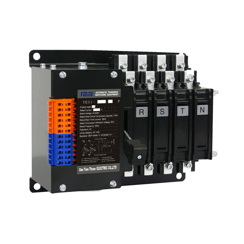
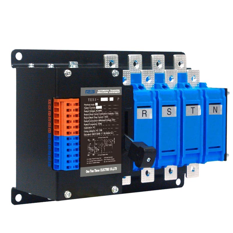
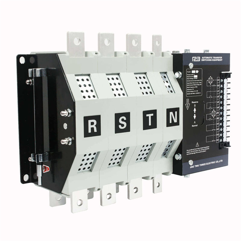
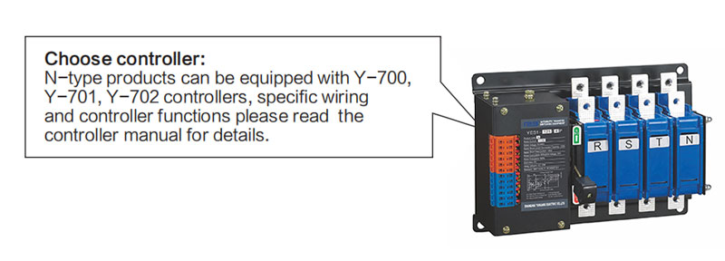
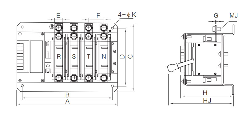
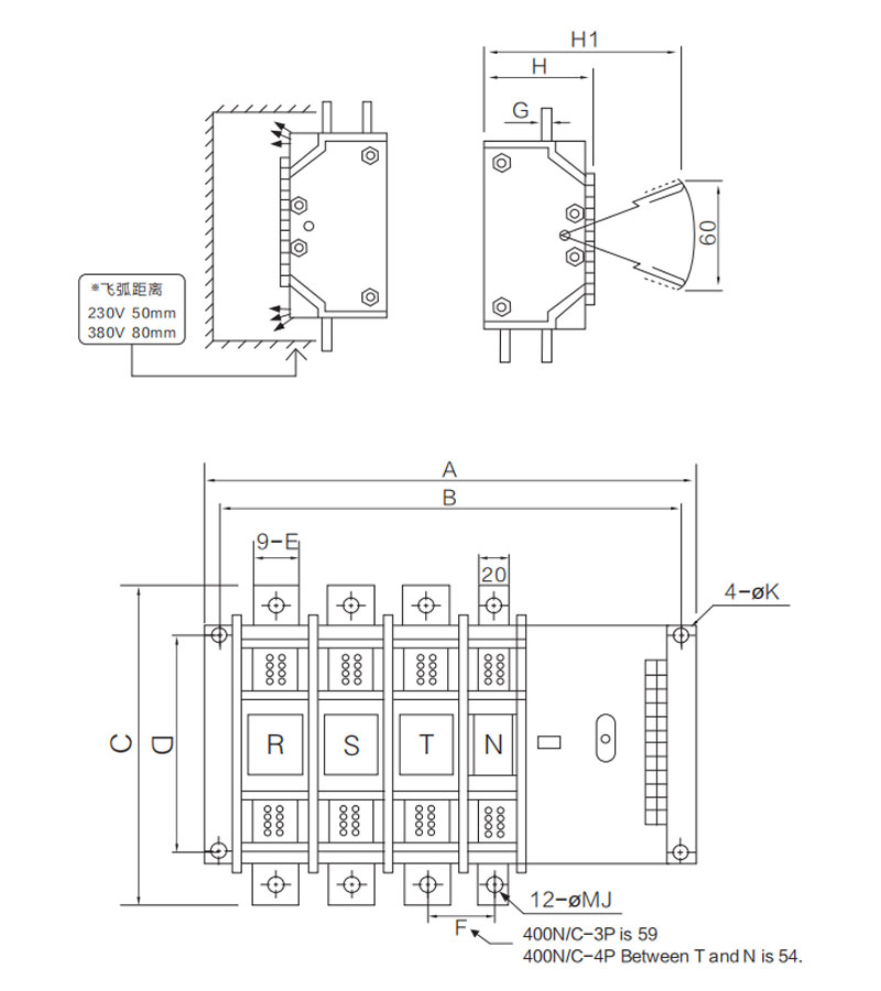
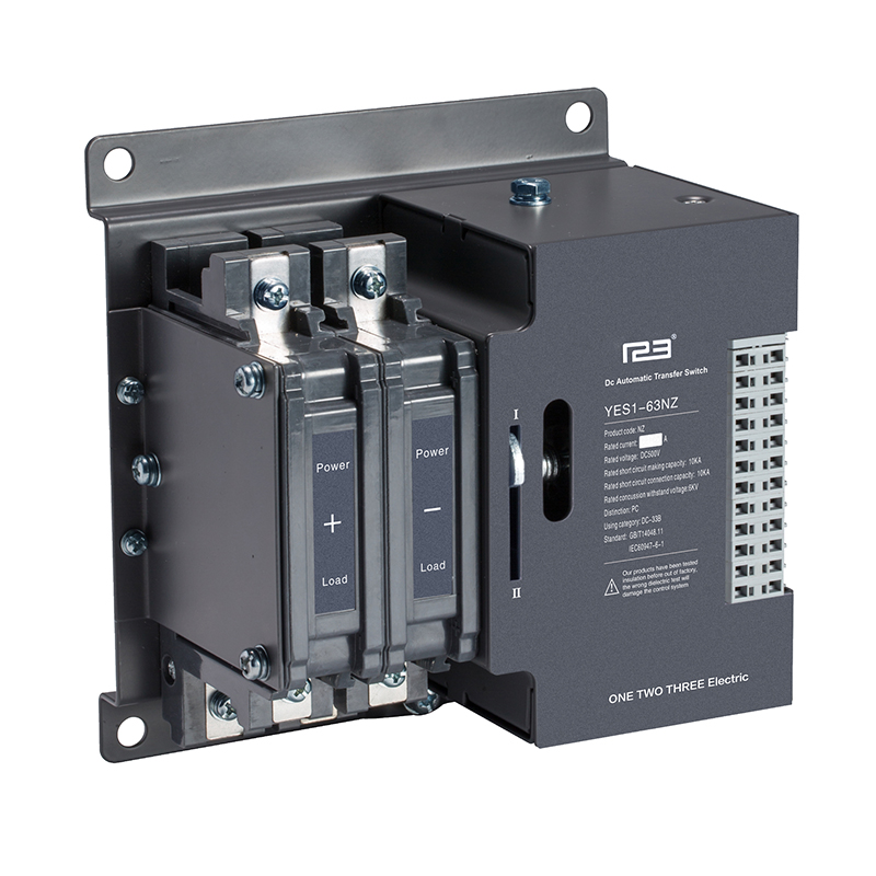
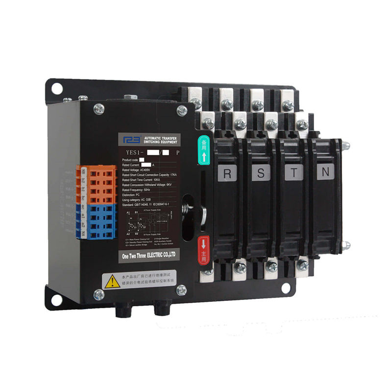
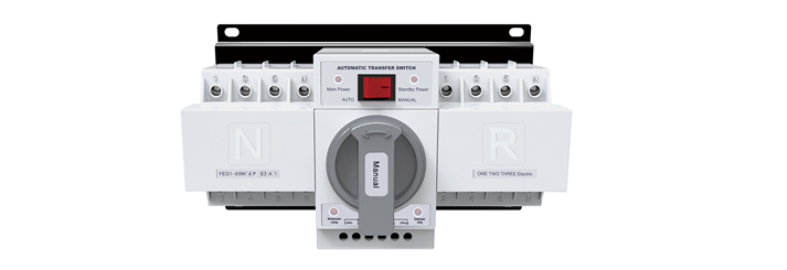
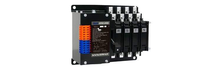
The work in the installation and commissioning of the product shall be carried out by professionals or those who have knowledge of the switchgear. Corresponding protection and precautions must be taken into account during operation. The main circuit of the switch must be wired in such a way that the leads are not subjected to any pressure or force.Before installation and commissioning, checking that the switch is not damaged or any other hazardous environmental impact, and it also should check whether the thread is loose due to transportation. Remove dirt, especially the dirt on the surface of the insulationparts. When connecting the primary circuit, it should be noted that the phase sequence of the normal power and standby power must be the same. When connecting the secondarycircuit control loop, it should be strictly in accordance with the wiring diagram in Instruction manual while paying attention to the control power supply voltage level, the switch must be installed with good grounding.
Pre-commissioning of products
Considering personal safety and switching speed, the debugging handle is only used for debugging. Users is not allowed use the debugging handle with load operation. And it is not allowed use when the arc extinguishing device is not installed. When debugging, the switch is operated with the debugging handle .To observe the close of the main contact and Running conditions.All are no abnormal situation, then the ATS switch can be work.
1. After debugging Controller and part of mechanical ,the controller and electrical part can be adjustedof the power-on debugging, the load is prohibited during the debugging process.
2. Put in the normal power into the products, the normal power indicator is light up, and then put in the standby power ,the standby power indicator is light up. and press the“Manual/Auto” button is placed in the manual position,Then press the "main power manual" button,The ATS will transfer to Main power quickly, The normal power indicator and external connecting indicator lamp is light up.Press the "standby power Manual", The ATS will transfer to Standby power quickly, The standby power indicator and external connecting indicator lamp is light up.
3. The "Manual/Auto" buttonis placed in the automatic position, delay time of normal power and standby power are adjusted to the appropriate value. The normal power supply is disconnected first, and the indicator of normal power Switch on is flashed on. When reached the setting of delay time value, The ATS will quickly switch to standby power supply automatically.The standby power indicator and external connecting indicator lamp is light up.
When the main power is return,the ATS will switch to Normal power supply, the indicator of standby power switch on is flashes, When reached the setting of delay time value, the ATS will quickly transfer to the normal power supply, The normal power indicator and external connecting indicator lamp is light up.
Use of products
1. In normal using, the controller should be placed in the automatic position ,The ATS is in the automatic control mode, The controller monitors both the main power and the backup power simultaneously and displays status. When the main power source has failure, such as power cut, under-voltage, over-voltage, or phase loss, The ATS will transfer to Standby power automatically. The power delay time is in 0~30 second. When the main power return, the ATS will transfer from Standby
power to Main power automatically. The controller is provided with a light-emitting diode to indicate condition of switch and power supply.
2. If you do not want the ATS switch automatically, or When other manual operations are required, you should set the controller in Manual position. When it is in Manual mode, the ATS is not transfer automatically.
3. When the ATS is in automatic mode,if the main power supply and the standby power supply are in normal condition. The ATS will give priority to connecting the main power supply to the load.
Common faults and Solutions
When the product does not work or work abnormally, first check the following points:
a. Is the switch body and the controller connected good or not? Is the connection correct?
b. Is the power turned on?
c. Is the controller in manual mode?
d. Is the voltage normal?
e. Is the switch body and the controller of main and standby power inputs opposite?
f. Is the fuse intact?
g. Is the debug line too long when debugging? Is the wire diameter too thin?
h. Whether to distinguish between neutral line N , phase line and PE ground line during debugging?
After-sales service
This series of dual power automatic switch is a high-tech product developed by our company using the latest technology. It is high reliability and guarantee,In the operation, abnormal phenomena may occur. If the problem cannot be solved according to the above points, please contact our after-sales service department.

